Rolling car – pressurizing device
The pressurization of the rolling car is achieved through a special pressurizing mechanism. The pressurizing device can be divided into a heavy hammer lever pressurizing device, a hydraulic pressurizing device and a pneumatic pressurizing device according to different pressurizing methods.
1. Heavy hammer lever pressurizing device
Heavy hammer lever pressurizing device is a pressurizing device with a long history of use and a relatively simple structure. Figure 3-2 shows a heavy hammer lever rolling mill.
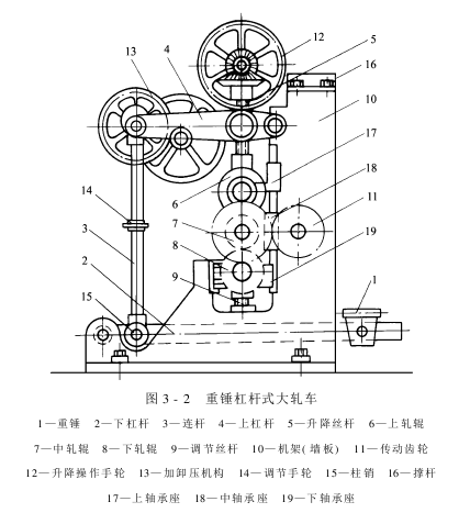
Heavy Hammer Lever pressure is applied to the roller through the weight, lower lever, connecting rod, upper lever, and lifting screw. The weight of the heavy hammer is limited. How much pressure can it generate after passing through the lever? We can calculate it based on the lever principle. Figure 3-3 shows the schematic diagram of the lever pressing mechanism of the three-roller rolling mill.
Let W1 and W2 be the weight of the upper and middle liquid rolling rollers and their two bearings and bearing shells, and W3 be The weight of the weight, the lifting screw and the connecting rod are all in a vertical state. The weight of the upper and lower levers, connecting rods, screws, etc. are not included for the time being. Then the respective pressures of the upper and lower rolling points are:
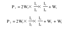
It can be seen from the above two formulas that if the leverage l1 , l 2 , l3 , l 4 have been determined, then the sizes of P1 and P2 mainly depend on the size of W3. When designing a new rolling mill, the reasonable lengths of l 1 , l2 , l3 , and l 4 should be considered.
From the calculations of the above two formulas, it can be seen that the pressures P1 and P2 at the upper and lower rolling points of this three-roller station rolling mill are not equal. The former is smaller than the latter. Usually the linear pressure at the rolling point is 392~882N/cm.
The heavy hammer lever type rolling car has a simple structure and is easy to maintain. However, this kind of rolling car often causes the lever to vibrate due to changes in the thickness of the fabric between the rollers, causing large fluctuations in the pressure at the rolling point. It is not convenient to operate and often needs to be stopped for manual operation, making it inconvenient for continuous production. Moreover, the leverage ratio of this kind of rolling car is limited by the machine footprint and the size of the fulcrum pin, so the pressure at the rolling point is also limited. Therefore, it is rarely used now.
2. Hydraulic pressurizing device
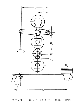
Adopt hydraulic pressurizing device , overcoming the shortcomings of lever pressure. Figure 3-4 shows a schematic diagram of the oil circuit system of the hydraulic pressurizing device. Its working principle is that the prime mover drives the oil pump, presses the oil from the oil tank into the oil cylinder, and then transports it to both ends of the lower roller through the three-phase valve and parallel pipes. The oil cylinder under the bearing pushes the piston, lifts the lower and middle rollers, and presses them against the fixed upper roller to complete the pressurization.
The hydraulic pressurizing device has the following advantages:
(1) Easily obtain higher pressure: The basic principle of hydraulic pressurization is to use the pressure transmission of sealed oil. The oil enters the pressurized cylinder through the pipeline. The pressure acts on the large area of the piston, so that greater pressure can be obtained.
(2) Easy operation: Hydraulic pressurization utilizes the piston of the pressurizing cylinder, which can reciprocate along the inner wall of the cylinder under different pressures, causing the bearing seats at both ends of the roll to slide up and down along the frame for pressurization and pressure relief. Since the liquid pressure in the seal is controlled by the pressure regulator, both ends of the roller can be pressurized evenly. It adopts valve control and is very convenient to operate.
(3) Relatively safe: Hydraulic pressurization does not have the risk of explosion like air pressure pressurization.
(4) Hydraulic pressurization In order to prevent the rapid drop in oil pressure caused by oil leakage, a pressure stabilizing device is often required to maintain stable pressure. Coupled with the hydraulic system’s pumps, various valves, oil filters, fuel tanks, piping systems, etc., it becomes more complicated and the equipment costs are higher. In addition, the hydraulic system must have good sealing to prevent oil leakage and staining of fabrics.
3. Air pressure pressurizing device
Air pressure is used more and more widely in pressurizing equipment in dyeing and finishing machinery. This is because the air pressure pressurizing device has the following advantages:
(1) Simple structure and easy operation convenient.
(2) The air flow rate is fast and the operation is fast.
(3) Convenient for remote operation and centralized control.
(4) It is relatively clean and will not contaminate the fabric due to leakage.
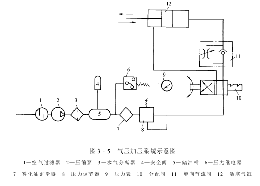
At the same time, due to the compressibility of air, when the thickness of the fabric passing through the nip point of the roller changes, the pressure of pneumatic pressurization changes slightly. The rolling residue rate is relatively uniform and the pressure fluctuation is small. Figure 3-5 is a schematic diagram of the air pressure pressurization system.
Air passes through The air filter removes dust and enters the compression pump for pressurization. Clean and dry compressed air is stored in the air storage barrel through the water and air separator. The barrel is equipped with a safety valve to prevent explosion due to excessive pressure in the barrel. The compressed air in the gas storage barrel passes through the atomized oil lubricator, mixes with the atomized oil, and then passes through the pressure regulator, distribution valve, and unit.�The throttle valve enters the cylinder and pushes the piston to pressurize the roller.
Figure 3-6 and Figure 3-7 are the structural schematic diagrams of a single-piston cylinder and a double-piston cylinder respectively. The latter increases the pressure of the pressurizing mechanism without increasing the diameter of the cylinder.
In addition to the above-mentioned piston cylinder pressure mechanism, there is also a membrane Air chamber type and air bag pressurizing mechanism.
Generally, the pressure of compressed air used for air pressurization is about 392kPa. Therefore, equipment with a total pressure at the roll point of more than 98000N is generally not suitable for air pressure pressurization devices because the pressurization mechanism is too large and uneconomical. Since compressed air may cause the container to explode, attention must be paid to the safety of the air pressure pressurizing mechanism during the design, manufacturing, and use processes.
AAAWQ32RDRGFJ
Extendedreading:https://www.alltextile.cn/product/product-76-620.html
Extendedreading:
Extendedreading:
Extendedreading:
Extendedreading:
Extendedreading:
Extendedreading:
ExtendedReading:
Extendedreading:
Extendedread