Hot air drying machine——cloth needle clip type hot air drying machine
Figure 5-23 and Figure 5-24 are the structural diagrams of cloth clip type and pin clip type hot air drying machines respectively. They are mainly used for drying after tenter finishing, sizing and resin finishing of cotton fabrics, drying of pad-dyed DT whitening agent for polyester and its blended chemical fiber fabrics and heat setting after tentering, etc.
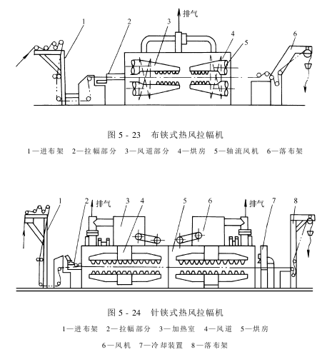
cloth ( The needle type hot air dryer is mainly composed of cloth feeding device, tenter device, heating device and air duct system, drying room, fan, exhaust, cloth discharge device and transmission device.
Its working principle is that there are many cloth clips (or needle clips) connected to form two long chains on the left and right. An automatic amplitude adjustment and overfeeding device is installed at the entrance of the fabric, so that the fabric enters the “eight” shaped imported cloth in a loose state. (needle) clipper chain. After that, the two chains on the left and right gradually become parallel, and the fabric is clamped on the track and runs in the drying room. Under a certain weft tension, it is dried (or baked) by the high-temperature hot air ejected from the air nozzles blowing up and down. Drying), to achieve the purpose of drying or shaping. After the fabric leaves the drying room, it enters the cold air zone to cool it quickly and reduce the temperature of the fabric surface. Now we focus on the tenter part.
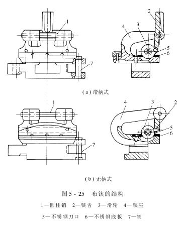
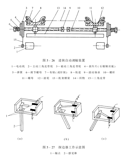
The tenter part mainly includes cloth (needle) clip chains and cloth guide plates, overfeeding devices, automatic amplitude adjustment devices for cloth feeding and edge detection, and transmission mechanisms. The structure of the cloth clip is shown in Figure 5-25, and there are two types: handle type and handleless type. The clip base is made of malleable cast iron, the bottom plate is a stainless steel plate, the brass clip tongue is inlaid with a stainless steel blade, and is equipped with a brass pulley. The clip tongue can swing at a certain angle around the cylindrical pin, and the pin connects many cloth clips into a ring. The whole machine has two annular cloth clip chains, which are respectively installed in the tracks composed of two horizontal cast iron guide plates on the left and right. The distance between the left and right guide plates can be adjusted to adapt to the width requirements of the fabric. There is an automatic amplitude modulation device at the entrance, as shown in Figure 5-26. Its movements are controlled by left and right edge detection devices.
Exploring the edge The device (i.e. edge detector) is a device installed before the fabric edge is inserted into the clip in order to keep the fabric edge in good contact with the cloth clip (or needle clip) and run in a certain position. One on the left and one on the left, to control the edge of the fabric before entering the tenter, so that the fabric can move left and right appropriately.
There are many types of edge detectors: reed type, full electric type and mercury contact type. Figure 5-27 shows a commonly used reed edge detector. The edge detector and the automatic amplitude modulation device jointly adjust the fabric edge. Figure 5-27(b) shows the situation where the edge of the fabric is in normal position, the contact rod is in a vertical state, and the amplitude modulation motor does not move; when the edge of the fabric moves outward to a certain position, the contact rod swings out accordingly, causing the connecting rod contact and the The upper contacts are in contact, as shown in Figure 5-27(a). The amplitude-modulating motor of this side rotates in the required direction, driving the cloth guide plate of this side to move outward; when the edge of the fabric moves inward beyond the normal position and reaches the position shown in Figure 5-27(c) In the displayed state, the connecting rod contact and the lower contact are in contact, and the amplitude modulation motor on this side drives the cloth guide plate to move inwards. In order to reduce the inertia generated when the motor stops rotating, a set of brake pads and pressure springs are installed on the outside of the triangle pulleys of the two amplitude-modulating screw rods.
Overfeed The device is that when the fabric is about to enter the cloth clip (or needle clip), the left and right edge parts are pressed by the two large and small rubber wheels of the cloth feeding device on the left and right sides respectively, and the cloth edge is rolled and sent to the cloth clip (if a needle clip is used, then The large brush wheel will roll the edge of the cloth towards the root of the steel needle, and the small brush will continue to press it to prevent the needle from falling off. If the cloth clip is used, the large and small brush wheels will be disabled). The large rubber wheel actively rotates so that the linear speed of the fabric when entering is slightly greater than the linear speed of the cloth clip (or needle clip) chain. Generally, the overfeeding rate can be controlled at 1% to 3%.
The working principle of the cloth clip is shown in Figure 5-28(a). At the cloth inlet end of the cloth clip chain, due to the action of the clip opening turntable above the cloth clip sprocket, the handle cloth clips around the warp turntable are opened, allowing the edge of the fabric to enter. When the cloth clip leaves the turntable, the pulley (Figure 5-25) is held by the edge of the fabric and cannot fall into the wheel groove of the bottom plate, and the knife edge does not clamp the fabric. When the opening of the cloth clip along this section of track gradually increases and the edge of the fabric moves outward to a certain position, the pulley falls into the wheel groove of the bottom plate, and the knife edge touches the edge of the fabric and clamps it, so that the width of the clip is even. . When removing the clips from the fabric at the outlet end, the same method is used to open the clip tongues. The handleless cloth clip uses an opening plate made of phenolic laminate to open the clip tongue, see Figure 5-28(b).
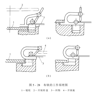
For prevention The fabric is detached, torn, and clipped during operation. The action of the clip tongue must be sensitive and reliable. The contact surface between the knife edge and the bottom plate of the clip base must be flush and seamless. The two outer sections of the knife edge must be in full contact, with no less than two points every 10 mm. You can use a 0.05mm thick piece of paper to test the clamp, and pull the two corners of the paper. There should be no loosening, hair clipping, or crushing. There should be no looseness and no cracking after the two ends of the cylindrical pin are turned outward and riveted. The corners around the bottom plate of the base need to be rounded.
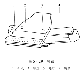
Needle clip The structure is shown in Figure 5-29. The needle plate is the main component of the needle clip. On the brass needle plate, there are slightly��The long needle (pointed needle) and the short needle (cylindrical needle) are equidistantly spaced outward (approximately 8°). When the edge of the fabric enters the needle clip, use two large and small brush wheels to press the edge of the fabric into the needle plate and pierce the fabric. The surface of the needle should be completely smooth, the needle should be sharp and without burrs, the long needle should pierce the edge of the fabric, and the short needle should prevent the edge of the fabric from continuing to penetrate downward. The long and short needles are tilted outward to prevent the pierced fabric edge from being pulled out in the weft direction and causing needle detachment. In this way, the fabric can no longer move in the weft direction.
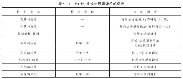
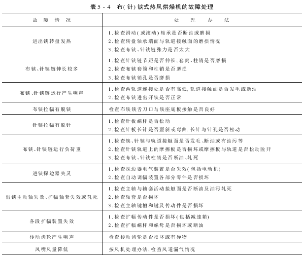
The maintenance precautions and troubleshooting of the cloth (needle) clip-type hot air dryer are listed in Table 5-3 and Table 5-4 respectively.

AAAFNJKIYO9P