Cylinder dryer – composition and functions of each part
The station-type drum dryer is mainly composed of a station column, a drying drum, bearings and seals, a water trap, steam inlet and drainage pipes, an expander and a transmission device.
The drum dryer uses steam for heating. The steam is passed from the steam main pipe into the hollow column of the dryer (or the steam pipe next to the grooved rectangular column), and is introduced into each drying cylinder respectively. Each steam inlet column (or steam inlet pipe) is equipped with a regulating valve, a safety valve and a pressure gauge. When the steam pressure per unit area exceeds the specified pressure, the safety valve will automatically open to release the overpressure. of steam. The steam entering the drying cylinder transfers heat to the drying cylinder, and then transfers the heat from the surface of the drying cylinder to the water-containing fabric surrounding the surface of the drying cylinder. The steam condenses into water due to the loss of heat, and the condensed water is discharged from the dryer through a drainage hopper or a siphon. tube, enters the stand column (or outlet pipe) at the drainage end, and is discharged out of the machine through the drain trap. Due to the function of the water trap, water and steam are prevented from being discharged at the same time.
The main parts of the drying drum dryer are the drying drum, the drying drum bearing and the water trap.
1. Drying cylinder
The drying cylinder is one of the main components of the drying cylinder dryer. The diameter is uniformly 570mm, and the working range can be 1100mm, 1200mm, 1600mm, etc. The wrapping angle of the fabric on the drying cylinder is 250°~276°. Large drying cylinders are also used on printing machines, with diameters of 1500mm, 2134mm or 2438mm. According to the material of the cylinder, the drying cylinder can be divided into two categories: copper drying cylinder and stainless steel drying cylinder; according to the different structure of the condensate discharge device, the drying cylinder can be divided into two categories: bucket type and siphon type drying cylinder.
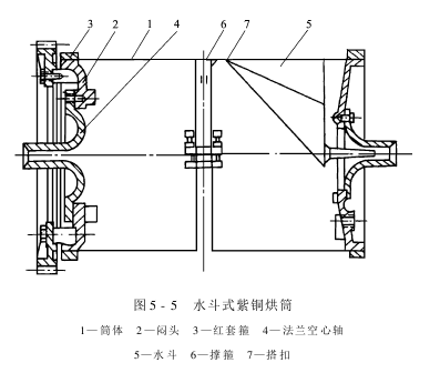
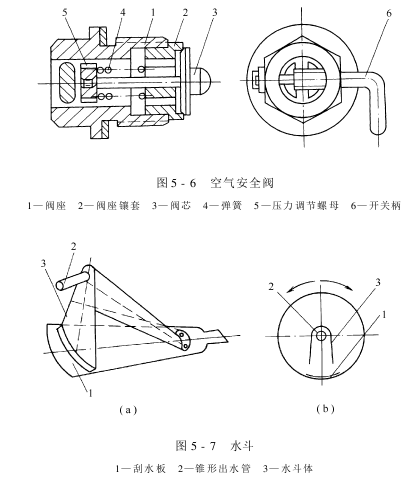
(1) Water bucket type copper drying cylinder as shown in Figure 5-5 As shown: The cylinder body is rolled with 2~3mm copper plate, and red ferrules are used at both ends to tightly connect the bulkhead and the cylinder body, and then screws are used to fix the flange hollow shaft on the bulkhead mouth. An air safety valve (Figure 5-6) is installed on the bulkhead at the non-drive end of the drying cylinder to prevent the negative pressure in the drying cylinder from being crushed (commonly known as “sucking”) due to negative pressure (such as when the car is turned on or stopped).
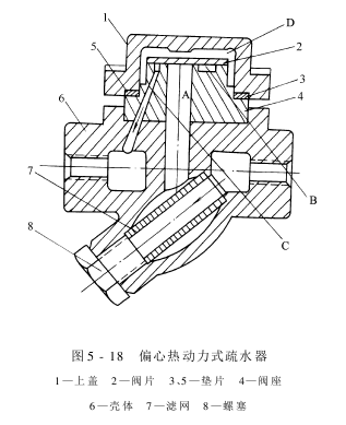
The structure of the water bucket is shown in Figure 5-7(a), and its working principle is shown in Figure 5-7(b). The water bucket is made of welded 2~3mm copper plate and is used to discharge the condensed water in the drying cylinder. The wiper blade is welded to the inner wall of the cylinder, and the conical water outlet connected to the water bucket body is inserted into the center hole of the flange hollow shaft (Figure 5-5). When the speed of the drying drum is low, the condensed water is concentrated in the lower part of the drying drum due to its own weight.
When the water bucket rotates with the drying cylinder to the lower part and encounters water, the water is scraped into the water bucket by the wiper; when the water bucket continues to rotate with the drying cylinder to the upper part, the water exits through the cone due to its own gravity. The water pipe drains out of the cylinder. Obviously, this bucket-type drainage device is corrosion-resistant, but it is only suitable for drum dryers with low rotation speeds.
There are support hoops installed inside the drying cylinder (Figure 5-5). The support hoop is an elastic ring made of HT15-33 cast iron. There is an open elastic joint on its circumference, and the diameter of the support hoop can be appropriately adjusted with screws. There are 7 notches evenly distributed on the outer ring to facilitate the circulation of condensed water in the drying cylinder. The purpose of adding support hoops is to improve the compressive strength of the cylinder and ensure the roundness of the outer circle of the drying cylinder. Generally, only one support hoop is installed on the drying cylinder. For wide drying cylinders (drying cylinders of 1600mm or above), two or more support hoops can be installed.
(2) Siphon type copper drying cylinder: Its structure is shown in Figure 5-8. The main difference between it and the bucket-type copper drying cylinder is the drainage method. The bucket-type drying drum relies on the gravity of condensed water to drain water, while the siphon-type drying drum uses siphon action to drain water. A siphon is a brass tube that is bent at one end. When driving, the condensed water accumulated in the drying cylinder is forced into the siphon tube by steam. Then, relying on the siphon effect and steam pressure, the condensed water can be continuously discharged out of the drying cylinder. Obviously, the smaller the gap between the curved end of the siphon tube and the inner wall of the drying cylinder, the less condensed water will remain in the cylinder during operation, and the higher the drying efficiency will be. However, since the other end of the siphon tube is fixed at the end of the air inlet cover, forming a long cantilever with poor rigidity, in order to prevent scratches on the cylinder wall, a certain gap should be maintained between its curved end and the inner wall of the drying cylinder. The distance between the siphon tube and the inner wall of the drying cylinder is normal. It should be controlled at 5~8mm.

Figure 5 -9 is the structural diagram of the siphon stainless steel drying cylinder. It is characterized by lightness, low transmission power, corrosion resistance, ability to withstand large pressure, and easy cleaning. However, since the thermal conductivity of stainless steel is smaller than that of copper, the drying efficiency is lower. Under the same drying conditions, the speed of the stainless steel drying cylinder should be about 10% lower than that of the copper drying cylinder to ensure the drying effect.
2. Drying cylinder bearings and sealing components
In addition to supporting the drying cylinder, the drying cylinder bearing must also seal the steam introduced into the drying cylinder or the condensed water discharged from the drying cylinder. Currently, three types of seals are widely adopted: packing seal type, plane seal type and spherical seal type.
(1) Packing sealed drying cylinder bearing: as shown in Figure 5-10. The steam passes through the steam inlet hole of the bearing seat and directly enters the inner hole of the drying drum shaft head. Adjust the compression screw to compress the spiral asbestos rubber filler through the gland, causing radial shrinkage and forming a rotating motion with the shaft head.w.zuranmianliao.cn/Uploads/image/20210510/c1kvqcnxmcn.png”>
When part of the steam and condensed water enters the steam trap through the filter screen at the bottom of the steam trap, the bucket will collapse due to the steam pressure. It floats and drives the valve disc to close the valve seat through the connecting rod to prevent steam leakage. At the same time, as the temperature inside the bucket rises, the spring leaf is heated and stretches, and the cover at the end of the spring leaf closes the drainage hole on the bucket, allowing the inside of the bucket to drain. The pressure increases, and a water level difference appears between the inside and outside, as shown in Figure 5-17(a). As the condensate water continues to flow in, part of the steam condenses, the steam pressure in the barrel decreases, and the water level rises, as shown in Figure 5-17(b). When the position is determined, the metal spring leaf shrinks due to cooling, the drain hole valve cover opens, and a large amount of condensed water enters the bucket. The bucket sinks due to its own weight. Through the connecting rod, the valve disc is opened to discharge the condensed water, see Figure 5- 17(c). When the condensate water is discharged to a certain amount, the steam enters the bucket, the temperature rises, the spring plate is heated and stretches to close the valve cover, and the bucket floats to close the valve disc, and the second cycle begins.
This type of water trap has reliable start-up, can continuously discharge saturated water and unsaturated water, has good operating performance, simple structure and small size.
③ Working principle of eccentric thermodynamic steam trap: Figure 5-18 shows the eccentric Thermodynamic steam trap. It is mainly composed of a shell, an upper cover, a valve plate, a valve seat filter, etc. It uses the principle of thermodynamics to block steam and drain water.
When the condensed water flows from the inlet through the filter to hole A. , when it reaches the bottom of the valve plate, the steam in the pressure transformer chamber D, annular groove B and outlet pipe C condenses due to the temperature drop, causing the pressure to decrease. Under the action of steam pressure, the condensed water opens the valve plate and passes through the annular groove. B, discharge from hole C, see Figure 5-19(a)

When the steam enters the steam trap, because the outlet hole C is smaller than the inlet hole A, the steam encounters resistance and enters the pressure transformer chamber D along the edge of the valve plate, as shown in the figure As shown in 5-19(b). As the steam continues to flow into the pressure transformer chamber D, the indoor pressure increases. At the same time, when the steam flows toward the hole C at a high speed along the annular groove, a negative pressure will appear around it according to the principle of thermodynamics. area, causing the pressure below the valve plate to be less than the pressure above it. Coupled with the weight of the valve plate itself, the valve plate will fall rapidly, closing the channel and blocking the continued leakage of steam, as shown in Figure 5-19(c). Show. Due to the heat dissipation of the water trap, the steam in the pressure transformer chamber condenses, which reduces the pressure in the pressure transformer chamber.
When the condensed water flows into the trap again, the above cycle will be carried out again.
This type of water trap has relatively good performance, large hydrophobic capacity, simple structure, small size, long service life, and convenient maintenance.
(2) Selection of water trap: The selection of water trap is mainly considered from the aspects of working temperature, working pressure and drainage volume. Generally, the maximum medium temperature allowed by a steam trap is 250°C and the maximum working pressure is 980kPa, which are both much higher than the steam temperature and pressure of the drying drum heating system. Therefore, the main consideration is the drainage volume. Generally, a drum dryer consumes 1.5kg of steam to dry 1kg of moisture, and accordingly produces 1.5kg of condensed water. Therefore, based on the high vehicle speed and the moisture content of the wet and thick fabric being dried, the condensed water discharged from the drying cylinder per hour can be calculated, and then this value is multiplied by the correction coefficient k (≈3), which is the selected drainage volume. basis.
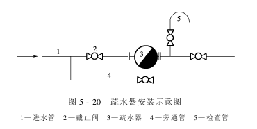
(3) Installation of the steam trap: As shown in Figure 5-20, the function of the direct discharge valve (also called the bypass pipe) is to speed up the process when there is a lot of condensed water before starting the vehicle or there is a lot of water accumulated in the steam trap. Drain the condensate. Sometimes there is debris in the trap that affects drainage, and a direct valve can be used to drain water directly. The function of the inspection pipe is to open the stop valve at any time to check the drainage condition of the trap.
(4 ) Precautions when installing the drain trap:
① The drain pipe should be close to and lower than the drying drum that discharges condensate water. The drainage pipe should have a certain slope to facilitate the discharge of condensate water.
②A bypass pipe and a straight-through valve should be installed next to the steam trap to discharge a large amount of condensed water and dirt when necessary or when driving. The bypass pipe cannot be installed under the steam trap.
③ Traps cannot be installed in series, but can be installed in parallel if necessary.
(5) Maintenance of steam trap:
① Regularly check the sealing between the valve seat, thimble, valve disc and valve disc. If there is steam leakage, repair or replace it immediately.
②Replace the water trap regularly, disassemble it for comprehensive inspection and verification.
③Regularly clear the debris in the drain trap (including the filter).
④ If the vehicle is parked for a long time in winter, antifreeze work should be done.
AAAVBBCNVM,N. KJO